S3 E-Type

Voltage Regulator
BUTEC R2

by Jaguar XJ6 Repair Manual

The description below shows a '60's-style' test of the Regulator. If you find yours is faulty and your electronics skills are limited (like mine), I suggest rather than going thru all these tests it's easier to just blindly replace all the semiconductor components - they are readily available (Transistors 2N3055, 2N2222, diodes 1N4003 & Zener 6.8V).

[At the bottom of the document I've added some pictures of my repair]

Also note that a modern Digital Voltmeter has a very high resistance: I found that I needed to load the output of the regulator with a 12V lamp in order to get the adjustment to work as expected.

DESCRIPTION
The BUTEC R2 regulator is a fully transistorised unit with no moving contacts.

butec-1.jpg


The components are fixed upon a printed circuit base in a sealed aluminium case which is suitably finned for heat dissipation. Output voltage adjustment is by a screw, accessible on removal of a socket plug in the front of the case.

ROUTINE MAINTENANCE
No routine maintenance is necessary.
Faulty components may be replaced as detailed under ‘FAULT FINDING.’

FAULT FINDING
The regulator unit is mounted on the left-hand wing valance adjacent to the alternator (XJ6). The purpose of this section is to instruct Service personnel in the correct test procedures, which, using common test equipment, quickly diagnose the exact source of the trouble. It is recommended that the following checks be carried out so that only the defective component is repaired or replaced. It is essential to ensure, that when a fault exists the regulator unit, prior to disconnecting, is faulty and is not due to a wiring error, loose connections or the alternator. Disconnecting the battery whilst the engine is running or reversing the battery connections will cause damage to the semi-conductors in both regulator and the alternator.Before testing the regulator in detail because of low voltage output, first remove the plug from the regulator and join together negative and field leads at connector plug; do not use the regulator terminals to join the leads together as a short may exist inside the unit. This enables the alternator to run full field and should the fault persist, it cannot be the regulator unit.

Test on the Car
Assuming that the fault persists, check the voltage adjustment setting.
1 — On normal load check that a voltage at least equal to the battery voltage exists between the positive (+) and the negative (—) terminals at the regulator.
2 — The control potentiometer may be incorrectly set; adjust to 14 volts on load.
3 — Note setting of control potentiometer, rotate fully clockwise and measure the voltage between the field and negative terminals; this must be less than 1.5 volts. If so the regulator is operating correctly; reset to the original position.
If the above tests confirm that the regulator is faulty, it must be removed for further testing.

Bench Tests
Connect a 12 volt battery to the positive terminals of the regulator and a voltmeter between the positive and field terminals. An Avometer or similar instrument is ideal. (Positive terminal of the meter to positive terminal of regulator).

butec-2.jpg

Test circuit diagram (showing the underside ofthe regulator)

1.Field Discharge Rectifier (1N4003) and Output Transistor (2N3055) Test with the regulator control at its normal setting the voltmeter will read battery voltage less about 1 volt. If the reading is near zero rotate the adjustment screw fully anti-clockwise.The voltmeter should now read battery voltage.Using a shorting link wire, join the negative terminal of the regulator to the base of the 2N3055 transistor. The voltmeter will now fall to within 1 volt of zero and removal of the link will allow the voltage to rise again.
These tests ensure that the field discharge rectifier is not short-circuited and that the 2N3055 output transistor is switching correctly.
butec-3.jpg
Testing Output Transistor & Field Discharge Regulator

2.Driver Transistor
Connect a 100 ohms resistor between the potentiometer slider tag and positive.
The voltmeter should now drop to within 1 volt of zero. Remove the resistor.
This test ascertains correct function of the driver transistor.

butec-4.jpg
 Testing driver transistor

3. Potentiometer and Zener Diode
Connect a fully charged battery (12.4 volts or more) as shown below. Rotate the potentiometer adjustment screw clockwise. Voltmeter should read 12 volts approximately. Rotate the adjuster screw anti-clockwise; reading obtained should be 1 volt or less. This check proves correct operation of the potentiometer and the Zener Diode.
butec-5.jpg
Testing potentiometer and Zener diode

From the foregoing tests 1, 2, 3, it is possible to diagnose any incorrect operation of a stage or component. Before proceding further it is necessary to remove the printed circuit from the housing and then remove the components from the base.

REMOVAL OF PRINTED CIRCUIT BOARD

Using a box spanner, remove five No. 8 UNF setscrews holding the board, also the nuts and cross headed screws securing the output transistor (2N3055). A soldering iron not exceeding 25 watts dissipation should be used on all joints, together with solder puller. Remove solder from around the base and emitter pins of the transistor (2N3055). The printed circuit board can now be lifted from the housing, care being taken not to lose or damage the mica washer or screw insulating inserts when the output transistor is removed.

COMPONENT TESTING
No attempt should be made to take these measurements whilst the components are attached to the printed circuit base. This would result in false measurements and wrong conclusions due to shunt circuits on the base. Always unsolder the components as detailed above, being careful not to use excessive heat.

Transistor Testing
An ohmmeter is required for the tests described below and it is most important that correct polarities are observed.The polarity of an ohmmeter internal battery can he quickly ascertained and noted for future use. Connect a 1.5 volt cell as shown below. If the readings are as shown then the ohmmeter battery will be as indicated.
This test is particularly important with combination instruments such as an Avometer, where the positive terminal may well be the negative of an internal battery.

butec-6.jpg
Checking ohmmeter polarity Method of Testing

(a) Connect the positive terminal of the ohmmeter to the base lead wire. Touch the negative terminal lead to
the Emitter and then to the Collector. These readings should be approximately equal and of low resistance.
(b) Connect the negative terminal of the ohmmeter to the Base lead wire. Touch the positive terminal to the
Emitter and then to Collector. The readings should be of considerably higher resistance in this case.
Figure shows the transistor connections viewed from the underside.

butec-7.jpg
TRANSISTORS VIEWED FROM UNDERSIDE

Note: No specific readings are given for the tests above, only High and Low Resistance. The actual value will depend upon the type of ohmmeter used and its internal battery voltage. Since the tests are essentially PASS/FAIL, if in doubt, replace the transistor.

butec-8.jpg
 Diodes used in Butec regulator

Diode Testing


The diodes used in the regulator are illustrated above. Again using the ohmmeter, connect the positive of the meter to the diode anode and the negative to the cathode; the meter should read LOW resistance. Negative to anode should obtain a HIGH resistance reading.

It is unimportant if the meter scale will not accommodate the HIGH reading, for the test is aimed to show a large difference when reversing polarity. Differences of at least 100:1 are normal.

Zener Voltage Test

This test allows the Zener diode to be checked for act breakdown voltage. Connect a 12 volt battery, the diode and a resistor betwi 100 and 470 ohms as shown below. Together with a volt D.C. voltmeter.If the Zener is satisfactory it will read approximately volts. However, unless the resistor chosen is of a greater value than 200 ohms, the components should not be connected for more than a few minutes.

butec-10.jpg

Here's my unit as removed:

butec_repair_2.jpg

The nameplate is held on by four rivets that can be levered out carefully:

butec_repair_5.jpg

The circuit board is really 'old school':

butec_repair_3.jpg

The passive components are normally OK, so just replace the diodes & transistors. Only problem is identifying the polarity of the 2N2222 or NTE123 (black device on lower right of board):

butec_repair_6.jpg

The board is covered with some coating to prevent corrosion: after soldering repair this with varnish (even nail varnish) or more correctly a 'conformal coating'.

butec_repair_1.jpg

Finally here's a cicuit diagram kindly sent to me from someone on the Jag-lovers mailing list who wishes to remain anonymous:
reg_circ_diag.jpg
Comments
Voltage Regulatorsin|04 Mar : 19:20
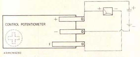
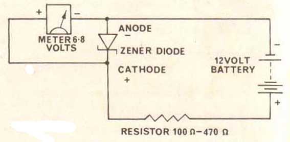
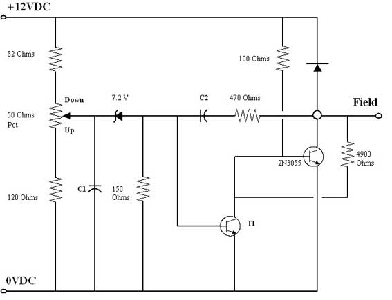
Guest


Reply to this
Does somebody have the circuit diagram of the Voltage Regulator? What should be the Battery Gauge reading when alternator is working well?

Re: Voltage RegulatorAdministrator |02 Apr : 09:16
Comments: 13


Reply to this
The most important point is the voltage at the battery when engine is running ~1500rpm.
If all is OK you should have 13.5 - 14 Volts. In fact, individual batteries require different voltages...you can adlust the regulator to supply that requirement. Do measure on the battery rather than at the regulator, as there's always some risk of voltage drop between the 2 and the battery charging voltage is what matters. Under these conditions the gauge in the car should be *just* in the charging region.

Voltage Regulatorwayne|13 Apr : 06:13
Guest


Reply to this
hi my e type series 3 ignition lamp stays on but only half brightness ? my control box seems to check over ok. but the at the battery terminals im measuring only around 12.6v at 1k revs and it dosent change at all?
a previous owner has fitted a new alternator and it looks all correct. any ideas as to what to look for please??

Re: Voltage RegulatorDave|16 Apr : 10:33
Guest


Reply to this
Hi, I replied by email. If you cannot get 13+V on the battery then it's either a field/output wiring problem or the alternator is faulty. You can eliminate the regulator disconnecting the field connection & by putting 12V on the field Wire ...alt should go into full charge >13V then...if it doesnt then wiring/alt are faulty.

Voltage RegulatorAnonymous|23 Apr : 02:50
Guest


Reply to this
hi dave, i have been checking over the alternator power connections on my car, i have found a blue plastic insulator/washer fitted to the negative post, this must act as an insulator for the post and therefor fail to make electrical ground. there is no electrical wiring to this post whatsoever i reckon this is the root cause of my fault?? what do you think? should the negative alternator post make ground? according to my circuit diag it should? the positive side is connected to the terminal located by the battery. your comments are very helpfull my end.

Voltage Regulatorn8apu@roadrunner.com|15 Jun : 11:34
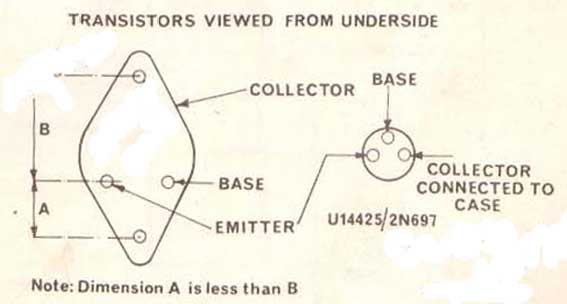
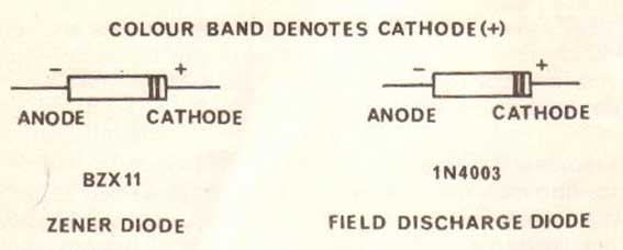
Guest


Reply to this
I have a 74. The parts are different. 1n4005, 2n3704, but i cant identify the zener, the markings on it 206? any idea

Re: Voltage RegulatorAdministrator |22 Jun : 07:45
Comments: 13


Reply to this
The Zener is the small bluish device about 4 0'clock relative to the potentiometer in the 2 pics of the circuit board above. You should be able to identify polarity by comparison with circuit diag.

Re: Voltage RegulatorAdministrator |24 Jun : 20:34
Comments: 13


Reply to this
Misunderstood your question...these are ancient components..when I looked-up the transistors one was described as the world's first commercially successful transistor... Even if the components differ in number I think that any 7.2V Zener will do

Voltage RegulatorOV1pilot@aol.com|17 Nov : 22:35
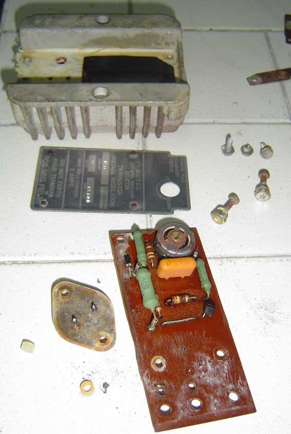
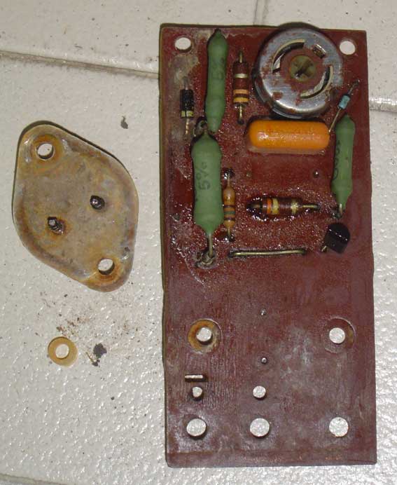
Guest


Reply to this
On the bottom of the regulator is a small, unmarked two lead component. Any idea what the component is and a replacement part number?

Re: Voltage RegulatorAdministrator |02 Feb : 21:23
Comments: 13


Reply to this
I think it's C1 on the diagram above

Voltage RegulatorSimon|07 Mar : 14:27
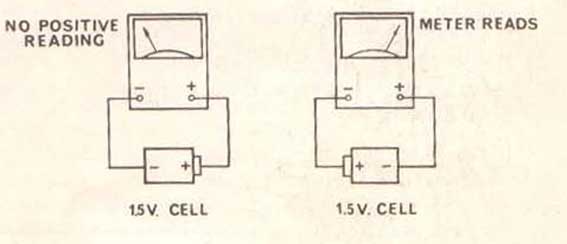
Guest


Reply to this
Hi, Congratulations on a fantastic site. I am in Australia and completing my own restoration of a 2+2 Series 3. I have alternator/regulator problems. When started for the first time, the charge light stayed on. I have tried to apply the tests described on the voltage regulator page of this site, but don't fully understand the procedure. I have 11.9 v at the battery with the engine running and all connections as normal. When I remove the plug from the regulator and join negative to field terminals, the voltage is still 11.9 v. The diagnostic manual on your site appears to indicate that the regulator is therefore not at fault. This seems hard to believe, as the alternator is rebuilt, whilst the regulator is untouched. Am I doing the diagnostic right and have you any suggestions as to where I can get further info/help?
Thanks,
Simon

Re: Voltage RegulatorAdministrator |14 Mar : 19:22
Comments: 13


Reply to this
Hi Simon,

If you pull the plug off the regulator and ground the wire that went to the field terminal (with engine running), the alternator will run at 'full strength'... you should see the voltage on the battery rise to 14+ ... don't let the car run long if that's the case as you'll boil the battery. If the voltage doesnt rise you either have a wiring problem or a faulty alternator.

dave

Voltage RegulatorAnonymous|10 Mar : 09:02
Guest


Reply to this
Thanks for all the info!

Does anyone know the caps specs?

Thanks very much!

Randy

Submit comment
Subject
Username:
Comment: